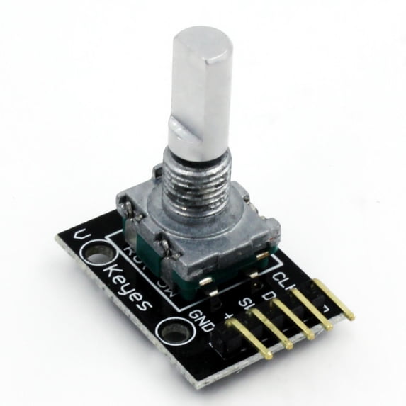
KY-040 Rotary Encoder Module with Pushbutton Switch
The KY-040 Rotary Encoder Module is a continuous 360-degree rotary input device with a built-in pushbutton switch. It outputs digital quadrature signals that let your microcontroller detect both the direction and amount of rotation. On-board 10K ohm pull-up resistors on all signal lines mean you can connect directly to an Arduino or other microcontroller with just jumper wires.
How It Works
- Connect the module's five pins (CLK, DT, SW, +, GND) to your microcontroller using jumper wires.
- As you turn the knob, two internal switches produce offset digital pulses on the CLK and DT pins.
- Your code compares the CLK and DT signals to determine which direction the knob is turning and how many steps it has moved.
- Press down on the encoder shaft to activate the built-in pushbutton switch, which pulls the SW pin LOW.
Specifications
- Model: KY-040
- Encoder Type: Incremental rotary encoder
- Operating Voltage: 5V DC (also works with 3.3V)
- Detents Per Revolution: 20 (18 degrees per detent)
- Pulses Per Revolution: 20
- Rotation: Continuous 360 degrees (no mechanical stops)
- Pushbutton Switch: Normally open, momentary (active LOW)
- On-Board Pull-Up Resistors: 10K ohm on CLK, DT, and SW
- Output Signal: 2-bit quadrature (Gray code)
- Module Dimensions: Approx. 30 x 18 x 30 mm (1.18 x 0.71 x 1.18 inches) L x W x H
What's in the Box
- 1x KY-040 Rotary Encoder Module (with knob shaft)
Jumper wires, microcontroller board, and knob cap are not included. Any standard 6mm D-shaft knob will fit.
Compatible With
- Arduino (Uno, Mega, Nano, Leonardo, Due, and compatibles)
- Raspberry Pi (all models)
- ESP32 and ESP8266
- STM32, Teensy, PIC, and AVR microcontrollers
Typical Applications
- Menu navigation and selection on LCD or OLED displays
- Volume and brightness controls
- Parameter adjustment (set points, thresholds, timer values)
- Stepper and servo motor speed and direction control
- CNC and 3D printer manual jog controls
- DIY audio equipment (amplifiers, mixers)
- Robotics steering and configuration input
Important Notes
- Mechanical encoders produce contact bounce. Use software debouncing or add 100nF capacitors between CLK/GND and DT/GND for clean signals.
- For best responsiveness, connect CLK and DT to interrupt-capable pins (Pins 2 and 3 on Arduino Uno).
- Keep jumper wires under 20cm (8 inches) to minimize electrical noise.